Mechanical 3D Design
Learning SolidWorks and modelling the repeating mechanical structure
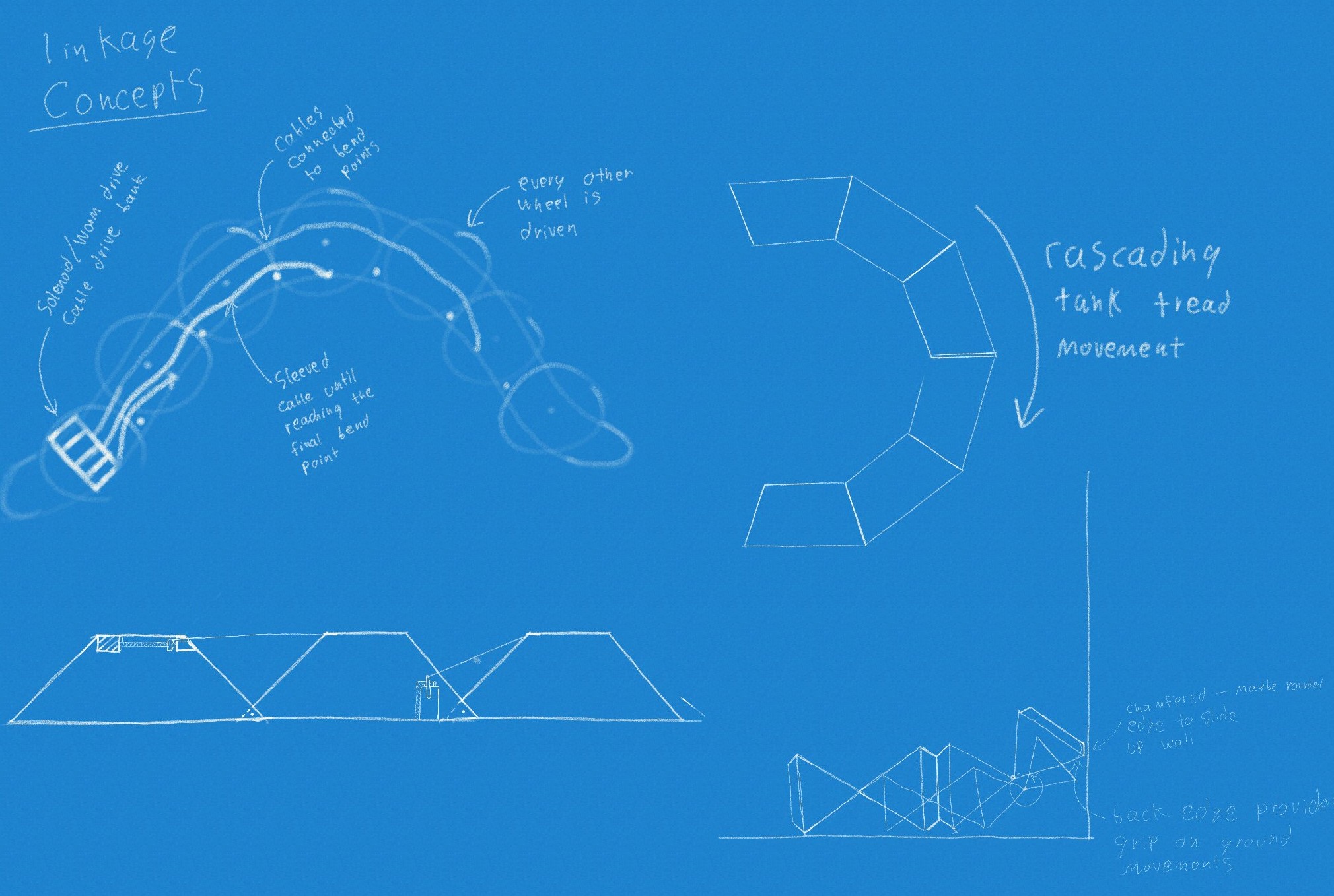
I love sketching, I’m not very good at it yet, but fleshing out an idea is always really exciting. One of my favorite makers, Adam Savage, constantly promotes the idea that even if you aren’t an artist, putting something on paper makes your idea more tangible. Organizing these drawings is still something I’m struggling but I managed to find a few (see left).
A lot of the snake module constraints came down to what I needed them to fit though. I had a general idea that I wanted them to alternate so the robot could move every other cell along the orthogonal axis of the last. This is very similar to the Matsuno Lab snake design. The budget constraints dictated that I use cheap actuators, so I decided on micro servos. They provide a good amount of torque for their size and can be driven directly with a PWM signal that most microcontrollers can generate.
With those design constraints in mind I just needed a piece that could connect one servo to the next, with some extra space for wire management and batteries. In the past I’ve used Autodesk Inventor and Fusion360 for all my 3D CAD work, but having recently gained an educational license for SolidWorks, I decided it was time to jump in and learn.
SolidWorks has way more options and tools than Fusion. And I mean way more. ALOT more. many. Have I made my point? It took me a while to get used to this, eventually I set up custom menus so I wasn’t searching for every tool each time I needed it. Now, I love it. As with any piece of software it comes with frustrations, but there is a way to do pretty much everything and a tool that makes it just a little bit easier. Now that I’m more comfortable with the workflow, I can branch out and try different methods of design. I can learn how to better optimize the design tree along the way, avoiding yellow exclamations and, heaven forbid, red x’s as best I can.
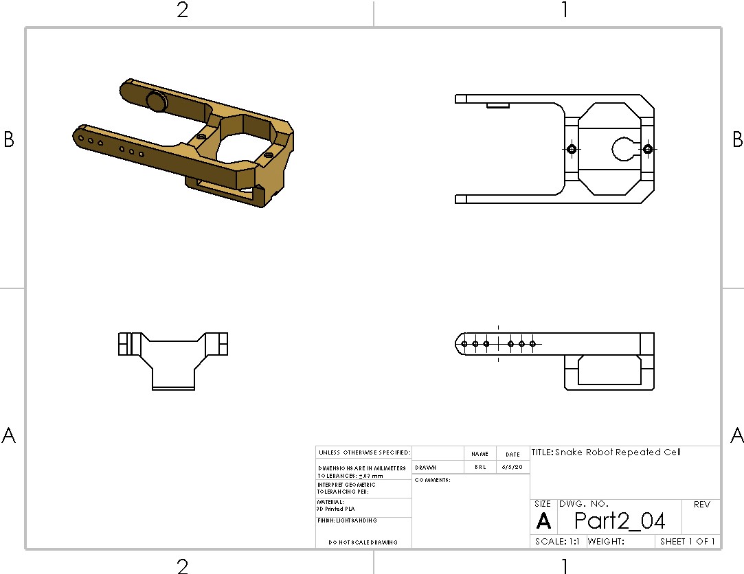
But, back to the design. It is pretty much completely based around the micro servo (SG90). The detailed drawing can be seen to the right and it shows how everything fits together. I’ve made the part available for download in STEP and SLDPRT formats if you want to take a closer look. It is fully 3D printable and requires only the two mounting screws for the servos. There are no bearings and no extra components needed.


