Deployable V-Wing Design
Designing micro spring loaded mechanisms
The rocket tube chosen by the propulsion team was small. It was a decision based on budget constraints and the current rocket motors possessed by the team. As this was truly our rookie year, having entirely new members, our budget was small and we had to use what remained. In hindsight, we should have collaborated more and found a way to get larger motors and thus a longer and larger diameter rocket tube. But, that idea comes with 20 20 vision and an omniscient understanding of the situation. At the time though, we had to make it work.
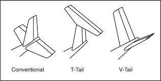
The solution was to go for a more compact tail that could fold neatly underneath the packed main wings. Introducing: the v-tail. You may be familiar with this concept, but if you’re not you can see it illustrated here. Also, for an ultra simple explanation see Flite Test’s write up. Using two separate surfaces the v-tail combines the function of a tradition elevator and rudder by using two “ruddervators”, its easy to see where that name came from. By mixing the position of the ruddervators, the same pitch and yaw (with a bit of roll) can be achieved, provided the driving software is tuned well.
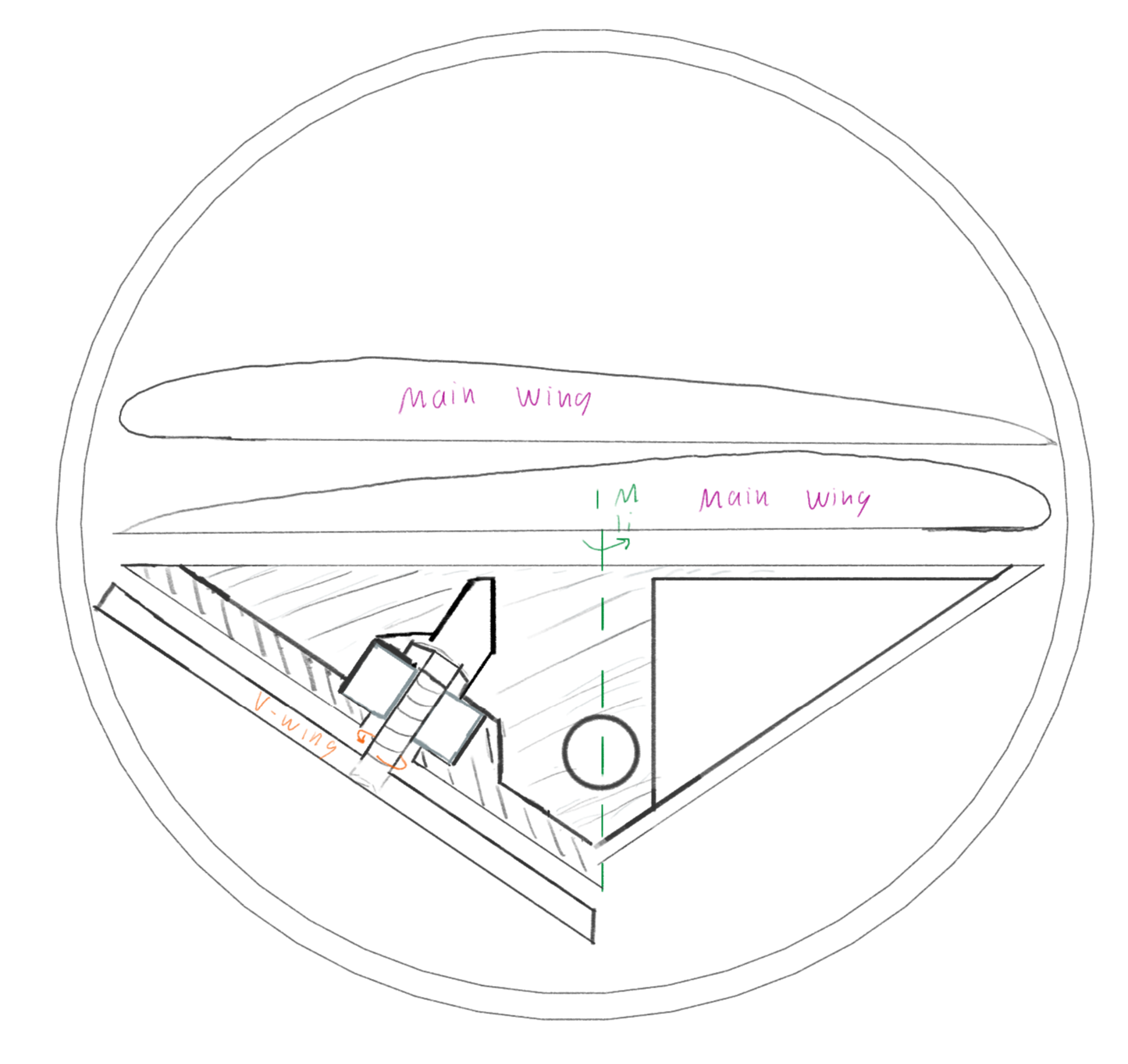
The v-wing can be seen used on several military UAV’s such as the predator drone (although it’s inverted and combined with a rudder) and the ever controversial Beechcraft Bonanza. For our purposes, it mattered that it could be packed small and use a smaller and lighter deployment mechanism than a traditional tail. I’ve included a crude early sketch that illustrates the space constraints. The outside ring is the rocket tube, the main wings are packed on top of eachother right in the middle of the tube to maximize their chord. The v-wing can then be packed at the necessary angle below the main wings. The length can then be “indefinite”, restricted by material strength.
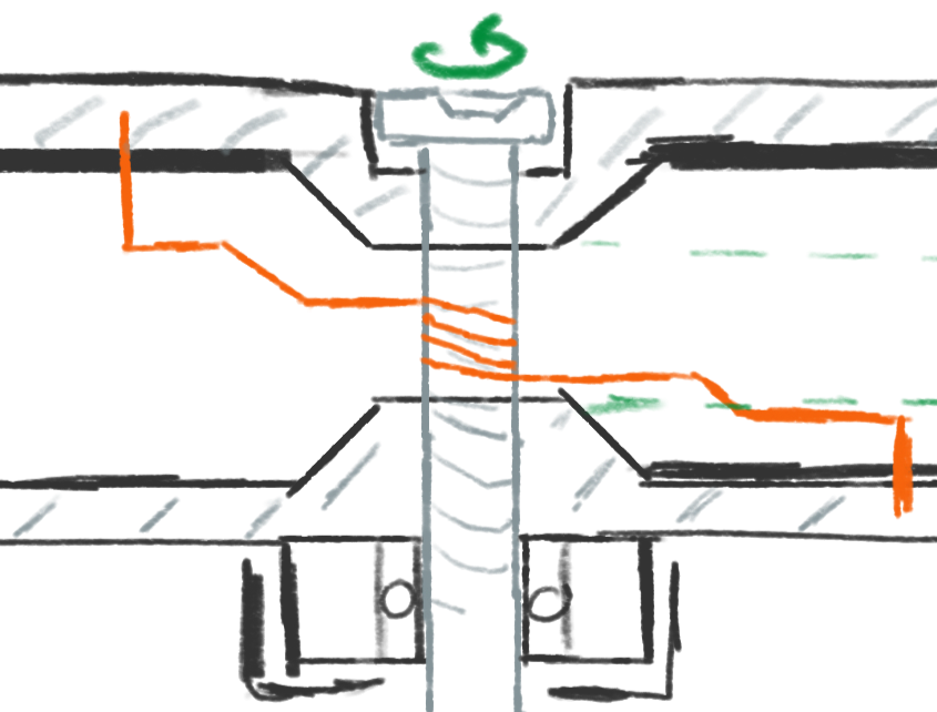
Fast forward a ton of iterative design and part sourcing and I came up with this. It’s a torsion spring loaded mechanism that uses a micro servo release that deploys two servos mounted to fiberglass, whose shafts are connected to thin carbon fiber rods that run through hot wire cut foam. Since the wing has such a short chord, the entire thing is a control surface. Sourcing the parts was probably the most difficult, the rotation mechanism runs on teflon tubing as opposed to bearings to reduce weight and size and the torsion springs are sized exactly for the torque needed. The housing is a 3D print sandwiched between two cut carbon fiber plates of which the back one is the motor mount. It’s a rather unique part and I learned alot about 3D modelling and keeping the physical limitations in your mind while doing so. Some of my initial designs ended up being too weak in areas, or the tolerances were just too tight to be printed. With experience I was able to avoid these issues in the future designs and create fewer iterations along the way.
A couple extra sketches from the initial design stages:


